Ever wondered how a simple ECG can reveal so much about your heart? It all comes down to the magic of leads on ECG—each one capturing a unique angle of your heart’s electrical activity. Let’s dive into what makes them so crucial.
Understanding Leads on ECG: The Foundation

The term leads on ecg refers to the different perspectives or views of the heart’s electrical impulses recorded by an electrocardiogram machine. These leads are not physical locations but rather mathematical derivations based on electrode placements on the body. Understanding them is fundamental to interpreting ECGs accurately, whether you’re a medical student, nurse, or physician.
What Are ECG Leads?
An ECG lead represents the difference in electrical potential between two or more electrodes placed on the body. Each lead provides a unique ‘view’ of the heart’s electrical activity, allowing clinicians to assess various regions of the myocardium. There are typically 12 standard leads used in a 12-lead ECG: 6 limb leads and 6 precordial (chest) leads.
- Limb leads: I, II, III, aVR, aVL, aVF
- Precordial leads: V1 to V6
- Each lead monitors a specific anatomical area of the heart
The configuration of these leads on ecg allows for comprehensive spatial analysis of cardiac depolarization and repolarization.
Historical Development of ECG Leads
The concept of ECG leads was pioneered by Willem Einthoven in the early 20th century. He introduced the standard limb leads (I, II, III), which form the basis of what we now call Einthoven’s triangle. His work earned him the Nobel Prize in Physiology or Medicine in 1924. Over time, additional augmented limb leads (aVR, aVL, aVF) and chest leads (V1–V6) were added to enhance diagnostic precision.
“The electrocardiogram is the most important method for studying the heart’s electrical activity.” – Willem Einthoven
Modern ECG machines now use these 12 leads as a standard, providing a multidimensional view of the heart’s function through carefully positioned leads on ecg.
Types of Leads on ECG: Limb vs. Precordial
One of the first things learners must grasp is the distinction between limb and precordial leads on ecg. Each type serves a different purpose and provides unique insights into cardiac function.
Limb Leads: The Frontal Plane View
Limb leads monitor the heart’s electrical activity in the frontal plane—the vertical plane that divides the body into front and back. These include the standard bipolar limb leads (I, II, III) and the augmented unipolar limb leads (aVR, aVL, aVF).
- Lead I: Measures voltage between right and left arms
- Lead II: Between right arm and left leg (often used in monitoring)
- Lead III: Between left arm and left leg
The augmented leads (aVR, aVL, aVF) are derived using a central terminal as a reference point. For example, aVR looks at the heart from the right shoulder, often showing inverted complexes due to its unique orientation.
These leads on ecg are essential for identifying axis deviation, limb lead infarcts, and rhythm abnormalities such as atrial fibrillation or heart blocks.
Precordial Leads: The Horizontal Plane Insight
Precordial (or chest) leads—V1 through V6—are placed across the chest wall and provide information about the heart in the horizontal plane. They offer a cross-sectional view of the ventricles, particularly useful in diagnosing anterior, septal, and lateral wall myocardial infarctions.
- V1 and V2: Over the right ventricle and interventricular septum
- V3 and V4: Transition zone; show evolving R waves
- V5 and V6: Over the left ventricle
Proper placement is critical. Misplacement of even one electrode can lead to misinterpretation of ST-segment changes or Q waves—key indicators of ischemia or infarction. The American Heart Association provides detailed guidelines on correct electrode positioning for accurate leads on ecg readings (American Heart Association).
How Leads on ECG Capture Heart Activity
The science behind leads on ecg lies in the heart’s electrical conduction system. Every heartbeat begins with an impulse from the sinoatrial (SA) node, spreading through the atria, then the atrioventricular (AV) node, down the bundle of His, and into the Purkinje fibers, causing ventricular contraction.
Electrical Vector and Lead Orientation
Each ECG lead acts like a camera pointed at the heart from a different direction. When the electrical wavefront moves toward a positive electrode, it produces an upward deflection (positive wave); when it moves away, it creates a downward deflection (negative wave).
- Leads facing the direction of depolarization show positive deflections
- Leads facing away show negative deflections
- Perpendicular leads may show biphasic waves
This vector-based interpretation is crucial for understanding patterns seen in conditions like myocardial infarction or bundle branch blocks. For instance, a deep S wave in V1 and tall R in V6 suggest left ventricular hypertrophy—a finding derived from analyzing multiple leads on ecg.
Waveform Components Across Leads
Each lead records the same basic components—P wave, QRS complex, T wave—but their morphology varies depending on the lead’s orientation.
- P wave: Represents atrial depolarization; upright in most leads except aVR
- QRS complex: Ventricular depolarization; varies significantly across leads
- T wave: Ventricular repolarization; usually follows QRS direction
In lead II, the P wave is typically upright, making it ideal for rhythm assessment. In contrast, aVR usually shows inverted P, QRS, and T waves because it ‘looks’ at the heart from the opposite direction. This variation across leads on ecg helps in localizing pathology.
Clinical Significance of Leads on ECG
The real power of leads on ecg lies in their ability to guide clinical decision-making. From diagnosing acute myocardial infarction to detecting arrhythmias, each lead contributes vital information.
Diagnosing Myocardial Infarction by Lead Location
One of the most critical applications of leads on ecg is identifying the location of a heart attack. ST-segment elevation in specific leads corresponds to the affected coronary artery territory:
- II, III, aVF: Inferior wall MI (right coronary artery)
- V1–V4: Anterior/Septal MI (left anterior descending artery)
- I, aVL, V5–V6: Lateral MI (left circumflex artery)
- aVR: May show ST elevation in left main coronary artery occlusion
For example, ST elevation in leads II, III, and aVF strongly suggests an inferior MI. Prompt recognition using these leads on ecg can trigger immediate reperfusion therapy, saving myocardial tissue.
A landmark study published in the New England Journal of Medicine showed that early ECG interpretation reduced door-to-balloon time in STEMI patients by over 30% (NEJM).
Arrhythmia Detection Through Lead Analysis
Different leads on ecg help classify arrhythmias by revealing P wave morphology, PR intervals, and QRS width. For instance:
- Atrial fibrillation: Absent P waves, irregularly irregular rhythm (best seen in lead II)
- AV nodal reentrant tachycardia: Pseudo-R’ in V1 or pseudo-S in II, III, aVF
- Ventricular tachycardia: Wide QRS, AV dissociation, capture/fusion beats (clear in multiple leads)
Lead V1 is especially useful for identifying supraventricular vs. ventricular tachycardias due to its clear view of atrial activity and bundle branch block patterns.
Proper Placement of Leads on ECG
Even the most advanced ECG machine cannot compensate for incorrect electrode placement. Misplaced electrodes distort the signals captured by leads on ecg, leading to false diagnoses.
Standard Electrode Positions
For a 12-lead ECG, 10 electrodes are placed as follows:
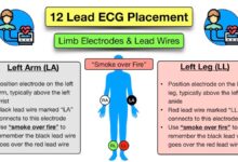
- RA (Right Arm): On the right upper limb, usually near the wrist
- LA (Left Arm): On the left upper limb
- RL (Right Leg): Ground electrode, on the right lower limb
- LL (Left Leg): On the left lower limb
- V1: 4th intercostal space, right sternal border
- V2: 4th intercostal space, left sternal border
- V3: Midway between V2 and V4
- V4: 5th intercostal space, midclavicular line
- V5: Anterior axillary line, same horizontal level as V4
- V6: Midaxillary line, same level as V4
Deviation from these positions—such as placing V4 too high or too lateral—can mimic anterior MI or mask real ischemic changes. The American College of Cardiology emphasizes standardized placement to ensure consistency in leads on ecg interpretation (ACC.org).
Common Placement Errors and Their Impact
Several common errors affect the accuracy of leads on ecg:
- Reversal of right and left arm electrodes: Causes lead I to invert, mimicking dextrocardia
- Incorrect V1/V2 placement: Can simulate right bundle branch block or anterior MI
- Swapped chest leads: Alters R wave progression, leading to misdiagnosis
A study in the Journal of Electrocardiology found that up to 40% of ECGs have some degree of lead misplacement, significantly affecting diagnostic accuracy.
“Accurate ECG interpretation begins with correct lead placement.” – Dr. Philip J. Podrid
Training and regular audits can reduce these errors and improve the reliability of data from leads on ecg.
Advanced Applications of Leads on ECG
Beyond the standard 12-lead ECG, advanced applications leverage leads on ecg for deeper insights into cardiac function and risk stratification.
Posterior and Right-Sided ECGs
In some cases, standard leads on ecg may miss posterior or right ventricular infarctions. Additional leads can be added:
- Posterior leads (V7–V9): Placed on the back to detect posterior MI
- Right-sided leads (V3R–V6R): Used when right ventricular involvement is suspected (e.g., inferior MI with hypotension)
ST elevation in V7–V9 confirms a posterior MI, often associated with occlusion of the left circumflex or right coronary artery. These extended leads on ecg are crucial in comprehensive cardiac evaluation.
Signal-Averaged ECG and Vectorcardiography
Signal-averaged ECG (SAECG) uses high-resolution processing of multiple cardiac cycles to detect late potentials—tiny electrical signals that indicate increased risk of ventricular arrhythmias. This technique enhances the diagnostic value of traditional leads on ecg.
- Used in patients with prior MI or cardiomyopathy
- Helps assess risk for sudden cardiac death
- Complements standard ECG findings
Vectorcardiography (VCG), though less common today, plots the magnitude and direction of electrical vectors in 3D space, offering a dynamic view beyond the 12 leads on ecg.
Interpreting Leads on ECG: A Step-by-Step Guide
Interpreting leads on ecg systematically ensures no critical finding is missed. Here’s a proven approach used by cardiologists worldwide.
Rate, Rhythm, and Axis
Begin with basic parameters:
- Heart rate: Count R-R intervals in lead II or use the 300-150-100 method
- Rhythm: Assess regularity and P wave presence in lead II
- Electrical axis: Use quadrant method with leads I and aVF
Normal axis ranges from -30° to +90°. Left axis deviation (e.g., in left anterior fascicular block) shows negative QRS in II and positive in I; right axis deviation shows the opposite.
Interval and Segment Analysis
Next, evaluate key intervals across leads on ecg:
- PR interval: 120–200 ms; prolonged in first-degree AV block
- QRS duration: <120 ms; widened in bundle branch blocks
- QT interval: Corrected for heart rate (QTc); prolonged in long QT syndrome
ST segment and T wave changes are assessed for ischemia, injury, or electrolyte imbalances. For example, ST depression in leads V4–V6 may indicate subendocardial ischemia.
Wave Morphology and Pathological Q Waves
Finally, examine wave morphology:
- Tall R waves in V1 may suggest posterior MI or right ventricular hypertrophy
- Deep Q waves in II, III, aVF indicate prior inferior MI
- Abnormal R wave progression in V1–V4 suggests anterior MI or conduction defects
Each of these findings relies on accurate interpretation of the 12 leads on ecg, highlighting the need for thorough training and experience.
What do the 12 leads on ECG represent?
The 12 leads on ECG provide 12 different views of the heart’s electrical activity. Six limb leads (I, II, III, aVR, aVL, aVF) view the heart in the frontal plane, while six precordial leads (V1–V6) view it in the horizontal plane. Together, they allow comprehensive assessment of cardiac rhythm, ischemia, infarction, and chamber enlargement.
Why is lead II commonly used for cardiac monitoring?
Lead II is often used in monitoring because it aligns well with the heart’s electrical axis, providing a clear view of P waves and QRS complexes. This makes it ideal for detecting arrhythmias like atrial fibrillation or heart blocks, where P wave analysis is crucial.
Can ECG lead placement affect diagnosis?
Yes, incorrect ECG lead placement can significantly alter the appearance of waveforms and lead to misdiagnosis. For example, swapping arm electrodes can mimic dextrocardia, while misplaced chest leads can simulate myocardial infarction. Proper training and adherence to guidelines are essential for accurate leads on ecg interpretation.
What is the significance of aVR in ECG interpretation?
Although often overlooked, lead aVR provides unique insights. It can detect global ischemia, left main coronary artery disease, or severe conduction disturbances. ST elevation in aVR with diffuse ST depression in other leads suggests a high-risk condition requiring urgent intervention.
How can posterior MI be detected if standard leads don’t show it?
Posterior MI may not show ST elevation in standard precordial leads because the infarct is on the back wall. Adding posterior leads (V7–V9) can reveal ST elevation. Alternatively, tall R waves and ST depression in V1–V3 may indirectly suggest posterior injury, prompting further investigation.
Understanding leads on ecg is not just about memorizing positions—it’s about seeing the heart through 12 different windows. From diagnosing life-threatening conditions to monitoring chronic disease, each lead plays a vital role. Accurate placement, systematic interpretation, and clinical correlation turn raw electrical data into actionable medical insight. Whether you’re a beginner or a seasoned clinician, mastering leads on ecg remains a cornerstone of cardiac care.
Further Reading: